
kalipso
Üye
- Katılım
- 25 Haz 2009
- Mesajlar
- 1
- Puanları
- 1
Arkadaşlar 4x4 lük sudokuları 7 inputla çözen bi devre yapmam gerekio outputları 16 tane 7-segment displayle vercez. İlk kısım inputlar falan Xilinx kartta olcak ikinci kısım diplay kısmı yani PCB yapcaz. İnternette araştırdım pek bşy bulamadm. Nası yapabilirim. Öneriniz var mı
İngilizce olarak daha ayrıntılı açıklama mevcut.
In this project every group will design a digital circuit that the circuit will solve a Sudoku problem on a given 4 x 4 display. Sudoku is a logic-based, combinatorial number-placement puzzle. The objective is to fill a 4×4 grid so that each column, each row, and each of the four 2×2 boxes (also called blocks or regions) contain the digits from 1 to 4 only one times each. The puzzle setter provides a partially completed grid referred as a set of input numbers
Each group will design the project on Xilinx environment and a hardware part also will be requested to visualize the game.
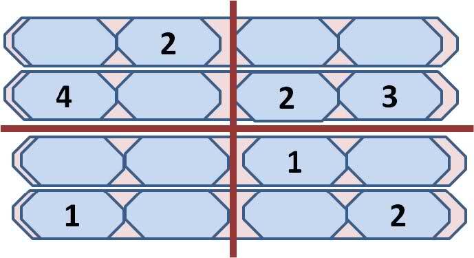
Possible input to the Xilinx Board is given in Figure 1. You will determine every cell of the puzzle as input and output so that the given combination will be input to the system and every other cell will be output of the system. You have to make some cross check to find the numbers. If a number is given to you, its dot in 7 segment display should be lid and only the input numbers' dots should be lid. It is guaranteed that a given input number set has exactly one solution.
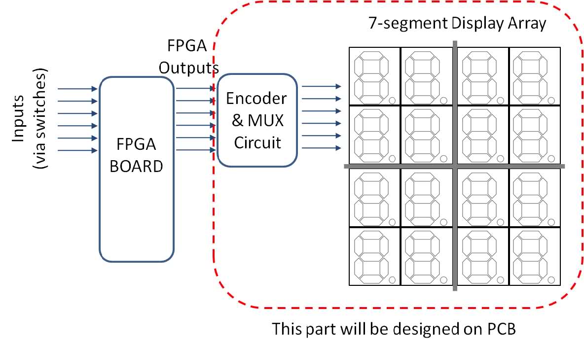
There will be sixteen 7-segment displays to demonstrate the output. Since Xilinx Boards have only four displays you have to design a circuit to drive sixteen 7-segment displays. The general view of the design, inputs and outputs are given in Figure 2.
Input numbers will be given by input switches therefore you will need a “DATA READY” switch to tell the system that your input data is ready. Once you take the input you will be ready to take the 2nd input data. Once inputs are finished than your circuit will start evaluating, therefore you will need an “EVALUATE” button to solve the puzzle. You have to show the solution step by step which means whenever you find a number you will update the play ground and show the number on the screen. You may find numbers fast but you should display them in an appropiate speed such that an observer can easily track which number comes. You have to select your display frequency properly so that observer tracks the solution one by one on the 7-segment display array. You have to give enough time to observer to observe the outputs one by one. Please be aware that scanning speed is different than update speed since encoder can blink one 7-segment display only.
To give insight about the project you may use 7 bit coding for each input value that is 4 bit of the input code will select the 7 segment display and 3 bit of the input code will decide the value of the number. Therefore 7 bit operation will be enough to complete the project. At the output you will have a 7 bit output, so you will need an encoder and multiplexer circuit to address the correct 7-segment display on the display array and show appropiate data. There will be lots of wiring at this stage, so each group has to prepare a PCB (printed circuit board) for this stage including encoders, multiplexers, 7-segment display array and any other necessary components on it.
İngilizce olarak daha ayrıntılı açıklama mevcut.
In this project every group will design a digital circuit that the circuit will solve a Sudoku problem on a given 4 x 4 display. Sudoku is a logic-based, combinatorial number-placement puzzle. The objective is to fill a 4×4 grid so that each column, each row, and each of the four 2×2 boxes (also called blocks or regions) contain the digits from 1 to 4 only one times each. The puzzle setter provides a partially completed grid referred as a set of input numbers
Each group will design the project on Xilinx environment and a hardware part also will be requested to visualize the game.
Possible input to the Xilinx Board is given in Figure 1. You will determine every cell of the puzzle as input and output so that the given combination will be input to the system and every other cell will be output of the system. You have to make some cross check to find the numbers. If a number is given to you, its dot in 7 segment display should be lid and only the input numbers' dots should be lid. It is guaranteed that a given input number set has exactly one solution.
There will be sixteen 7-segment displays to demonstrate the output. Since Xilinx Boards have only four displays you have to design a circuit to drive sixteen 7-segment displays. The general view of the design, inputs and outputs are given in Figure 2.
Input numbers will be given by input switches therefore you will need a “DATA READY” switch to tell the system that your input data is ready. Once you take the input you will be ready to take the 2nd input data. Once inputs are finished than your circuit will start evaluating, therefore you will need an “EVALUATE” button to solve the puzzle. You have to show the solution step by step which means whenever you find a number you will update the play ground and show the number on the screen. You may find numbers fast but you should display them in an appropiate speed such that an observer can easily track which number comes. You have to select your display frequency properly so that observer tracks the solution one by one on the 7-segment display array. You have to give enough time to observer to observe the outputs one by one. Please be aware that scanning speed is different than update speed since encoder can blink one 7-segment display only.
To give insight about the project you may use 7 bit coding for each input value that is 4 bit of the input code will select the 7 segment display and 3 bit of the input code will decide the value of the number. Therefore 7 bit operation will be enough to complete the project. At the output you will have a 7 bit output, so you will need an encoder and multiplexer circuit to address the correct 7-segment display on the display array and show appropiate data. There will be lots of wiring at this stage, so each group has to prepare a PCB (printed circuit board) for this stage including encoders, multiplexers, 7-segment display array and any other necessary components on it.